





BMS PCBA manufacturing for energy storage projects depends on disciplined control of design data, components, soldering, programming, inspection and electrical testing. The board also interacts with sensors, harnesses, connectors and structural parts, so interface management is as important as assembly. This guide focuses on component-level manufacturing support rather than complete cells, battery packs or energy storage systems.
Clarify the BMS PCBA scope
Define the board function, operating voltage range, sensing channels, communication interfaces, programming needs and connection points. Manufacturing data normally includes Gerber or ODB++, BOM, centroid data, assembly drawings and test instructions. Identify safety-critical or sourcing-sensitive components in the quotation package.
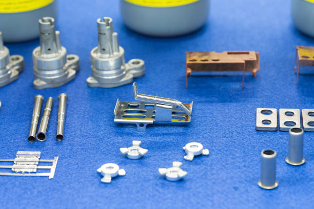
ECO ELECTRONICS coordinates energy storage component solutions through qualified partners. The scope can include BMS PCBAs, related wire harnesses, connectors and selected structural components according to the project data.
Control components and approved substitutions
BMS designs may depend on specific semiconductors, isolated communication devices, current-sensing components and connectors. The BOM should identify manufacturer part numbers, acceptable sourcing channels and approved alternatives. Substitution decisions need engineering review because electrical and thermal behavior can change.
For long lifecycle programs, discuss availability and end-of-life risks before production. Record lot or date-code requirements where traceability is required. The PCBA manufacturing support page explains the wider sourcing and assembly route.
Plan programming and electrical testing
Programming steps should define the file revision, loading method, verification and serialization rules. Electrical test requirements may include power-up checks, communication verification, channel simulation or functional tests using customer-defined fixtures. The exact method depends on the design and program risk.
Agree on test ownership, fixture development, pass/fail limits and record retention before production. Sample validation should capture failures and corrective actions so the released process can be repeated.
Coordinate harnesses, connectors and structures
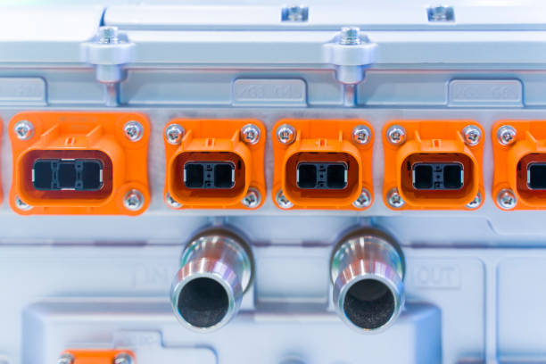
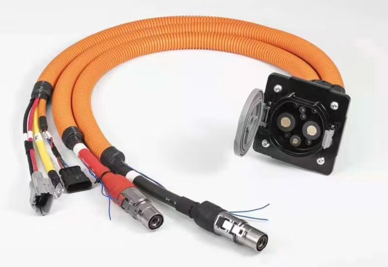
BMS boards connect to sensors, modules, communication networks and power interfaces. Connector keying, pinout, wire gauge, shielding, routing and strain relief must match the board and mechanical design. Early interface review reduces late-stage fit and wiring errors.
See wire harness manufacturing, connector support and precision component coordination for connected project elements.
Release production through documented checkpoints
Move from DFM to prototype, inspection, functional validation and approved production data. Track BOM revisions, firmware versions, test limits and approved deviations. Production follow-up should verify that changes receive approval before use.
The engineering and quality coordination process provides one project interface for supplier questions, sample feedback and delivery follow-up. Submit the technical package through the Request a Quote page for review.
RFQ checklist
- PCB fabrication and assembly data
- BOM with sourcing and substitution rules
- Firmware, programming and serialization instructions
- Electrical or functional test specification
- Harness, connector and mechanical interface data
- Traceability, packaging and delivery expectations
Frequently asked questions
What files are needed for a BMS PCBA quotation?
Provide fabrication data, BOM, centroid data, assembly drawings, firmware instructions, test requirements, quantities and delivery targets. Interface drawings help when harnesses or connectors are included.
Can BMS harnesses be coordinated with the PCBA?
Yes. Pinout, connector, wire, protection and test requirements can be reviewed as a connected project package.
Does this service include complete battery packs?
The current scope focuses on BMS PCBAs and related electronic, interconnect and structural components. Complete cells, battery packs and full energy storage systems require separate qualification.
How are firmware revisions controlled?
Define the approved file, revision identifier, programming method and verification record. Any firmware change should follow the project’s documented approval process.
Discuss your project
Send drawings, BOMs, quantities, quality expectations and delivery requirements. ECO ELECTRONICS will review the scope and coordinate a suitable manufacturing route.
